| Don’t just sit there! Build something!! |
学习数学分析电路需要大量的学习和实践。通常,学生通过处理许多样本问题并针对教科书或讲师提供的答案来练习。虽然这很好,但有更好的方法。
您实际上会学到更多building and analyzing real circuits,让您的测试设备提供“答案”,而不是书籍或其他人。对于成功的电路锻炼,请执行以下步骤:
避免使用741型运算放大器,除非您想挑战电路设计技能。初学者通常可以使用更多通用的操作AMP模型。我建议使用DC和低频AC电路的LM324,以及涉及音频或更高频率的AC项目的TL082。
像往常一样,避免了非常高且非常低的电阻值,以避免由仪表“加载”引起的测量误差。我建议在1kΩ至100kΩ之间的电阻值。
您可以节省时间并减少错误的可能性是从非常简单的电路开始,并逐步添加组件以增加每个分析后的复杂性,而不是为每个练习问题构建一个全新的电路。另一种节省时间的技术是在各种不同的电路配置中重复使用相同的组件。这样,您就不必多次测量任何组件的价值。
让电子本身给您解决自己的“练习问题”的答案!
It has been my experience that students require much practice with circuit analysis to become proficient. To this end, instructors usually provide their students with lots of practice problems to work through, and provide answers for students to check their work against. While this approach makes students proficient in circuit theory, it fails to fully educate them.
学生不仅需要数学实践。他们还需要真实的动手练习建筑电路并使用测试设备。因此,我建议采用以下替代方法:学生应该build他们与实际组件的“实践问题”,并尝试在数学上预测各种电压和当前值。这样,数学理论“生动起来”,学生就不会仅通过求解方程来获得实际的水平。
遵循这种实践方法的另一个原因是教学生科学的方法:通过执行真实实验来检验假设(在这种情况下,数学预测)的过程。学生们偶尔会造成电路施工错误,还将发展真正的故障排除技能。
花一些时间与您的班级一起审查一些“规则”,以便在它们开始之前进行建筑电路。与您的学生以相同的苏格拉底方式讨论这些问题,您通常会讨论工作表问题,而不是简单地告诉他们他们应该和不应该做什么。我从不停止惊讶学生在典型的演讲(讲师独白)格式中介绍时的指示程度!
A note to those instructors who may complain about the “wasted” time required to have students build real circuits instead of just mathematically analyzing theoretical circuits:
学生参加您的课程的目的是什么?
If your students will be working with real circuits, then they should learn on real circuits whenever possible. If your goal is to educate theoretical physicists, then stick with abstract analysis, by all means! But most of us plan for our students to do something in the real world with the education we give them. The “wasted” time spent building real circuits will pay huge dividends when it comes time for them to apply their knowledge to practical problems.
此外,让学生建立自己的练习问题会教会他们如何执行主要研究,从而让他们继续电气。工业l/electronics education autonomously.
在大多数科学中,现实的实验比电路更困难和昂贵。核物理学,生物学,地质和化学教授只会希望能够让学生将高级数学应用于真正的实验,从而不带安全隐患,而花费比教科书少。他们不能,但是你可以。利用科学固有的便利性,并让您的那些学生在许多真实的电路上练习数学!
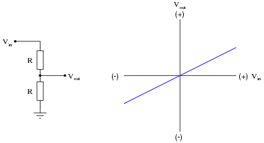
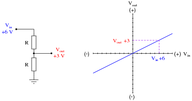
用于描述电子组件或子电路操作的一种常见图形是转移特征,显示输入信号和输出信号之间的关系。例如,简单电阻电压分隔电路的传输特性是一条直线:
|
|
Once a transfer characteristic has been plotted, it may be used to predict the output signal of a circuit given any particular input signal. In this case, the transfer characteristic plot for the 2:1 voltage divider circuit tells us that the circuit will output 3 volts for an input of 6 volts:
|
|
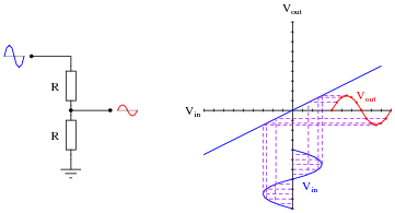
我们可以使用相同的传输特性巴解组织t the output of the voltage divider given an AC waveform input:
|
|
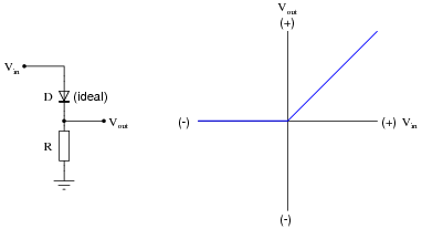
While this example (a voltage divider with a 2:1 ratio) is rather trivial, it shows how transfer characteristics may be used to predict the output signal of a network given a certain input signal condition. Where transfer characteristic graphs are more practical is in predicting the behavior ofnonlinear电路。例如,理想的半波整流器电路的转移特性看起来像这样:
|
|
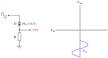
Sketch the transfer characteristic for a realistic diode (silicon, with 0.7 volts forward drop), and use this characteristic to plot the half-wave rectified output waveform given a sinusoidal input:
|
|

|
|
传输特征图提供了一种优雅的方法,可以为任何电网,线性或非线性的输出波绘制绘制输出波形。反映沿输入波形点的方法,并转移在输出波形上等效点证明了该分析工具的名称。确保您的学生有机会学习如何使用此工具,因为它可以很好地了解电子和电磁设备中的失真。
假设有硅二极管(0.7伏特的典型前向滴),请确定该电路的输出电压:

|
|
现在,用Schottky二极管(0.4伏特的典型前向滴)来确定同一电路的输出电压,而不是硅PN连接二极管:

|
|
现在,用发光二极管确定同一电路的输出电压(1.7伏典型的前向滴):

|
|
评论这三个电路的输出电压:这表明二极管电压下降对OPAMP输出的影响是什么?
在两个电路中,输出电压恰好为-2伏。
后续问题:什么is在这三个电路中有所不同,如果不是输出电压?
就这些电路本身而言,这些电路相当无用。他们的目的是使学生们通过表明负面反馈使二极管的正向电压下降如何无关紧要,以便让学生理解精确的整流器电路如何工作。这是负反馈力量的另一个例子,也是理解所有精确(OPAMP驱动)二极管电路的重要概念。
Determine the output voltage of this circuit for two different input voltage values: 5 volts, and -5 volts, assuming the use of ordinary silicon rectifying diodes:

|
|
基于此数据(以及您希望在下面测试此电路的任何其他输入条件),描述该电路的功能是什么。
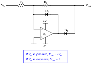
This opamp circuit is called a精密整流器。Analyze its output voltage as the input voltage smoothly increases from -5 volts to 5 volts, and explain why the circuit is worthy of its name:

|
|
Assume that both diodes in this circuit are silicon switching diodes, with a nominal forward voltage drop of 0.7 volts.
任何正面输入电压,无论多么小,都会在输出上“反映”作为相等(绝对)幅度的负电压。对于任何负输入电压,该电路的输出恰好保持在0伏。
后续问题:如果任一二极管的正向电压下降增加,它会影响输出电压吗?解释为什么能或者为什么不能。
与非撤消或非反转放大器电路相比,精确整流器电路对学生来说更难理解。花时间与学生一起在课堂上分析该电路,要求他们确定给定输入电压条件的电路(以及电流方向)中所有电压的幅度。
Understanding whether or not changes in diode forward voltage drop affect a precision rectifier circuit’s function is fundamental. If students comprehend nothing else about this circuit, it is the relationship between diode voltage drop and input/output transfer characteristics.
解释为什么以下操作员电路不能用作AC-DC电源电路中的整流器:

|
|
Here’s a hint: where does the opamp get its power from?
Believe it or not, I actually sat in an electronics class one time and listened to an instructor present the precision rectifier opamp circuit as a “precision rectifier for a power supply”. He was serious, too, claiming that this type of circuitry was used to provide split ( V/-V) voltage outputs for bench top power supplies. The saddest part of this ordeal is that none of his students recognized anything wrong with his statement (or at least did not feel comfortable in raising a question about it).
预测该精确整流器电路的操作将如何由于以下故障而影响。独立考虑每个故障(即一次,没有多个故障):
|
|
对于每个条件,请解释为什么the resulting effects will occur.
这个问题的目的是从知道什么是故障的角度来处理电路故障排除的域,而不仅仅是知道症状是什么。尽管这不一定是现实的观点,但它可以帮助学生建立从经验数据中诊断出故障电路所必需的基本知识。诸如此类的问题(最终)应遵循其他问题,要求学生根据测量结果确定可能的错误。
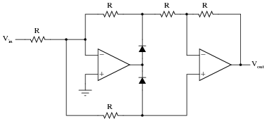
以下电路有时称为极性分离器。发明一些测试条件,您将用来“证明”电路的操作,然后在那些想象的条件下分析电路,并查看结果是什么:

|
|
为任何给定的输入电压说明每个输出在此“极性分离器”电路中的操作。
vOUT1输出是任何正输入电压的逆(负),而VOUT2输出是任何负输入电压的逆(正)。
该电路是对全波精密整流器电路的良好介绍,尽管其操作比这里更难理解。
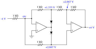
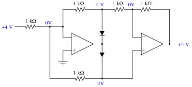
确定两个不同输入电压值的该电路的输出电压:4伏和-4伏。作为分析的一部分,确定每个节点的电压:

|
|
基于此数据(以及您希望在下面测试此电路的任何其他输入条件),描述该电路的功能是什么。
Explain how you could reverse the output polarity of this precision rectifier circuit:

|
|
|
|
The answer to this question may seem too obvious to both asking. In reality, it’s just another excuse to analyze the full-wave rectifier circuit, complete with all currents andvoltage drops呢
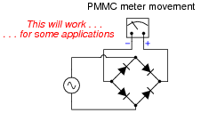
PMMC(永久磁铁移动线圈)的一个问题是试图使它们注册AC而不是DC。由于这些仪表运动对极性敏感,因此它们的针头在交替电流供电时以无用的方式来回振动:

|
|
同样的问题困扰着其他旨在与DC合作的测量设备和电路,包括最现代的模数转换circuits used in digital meters. Somehow, we must be able to纠正这些测量电路的测量AC数量在DC中,以正常运行。
一个看似明显的解决方案是使用由四个二极管制成的桥梁整流器来执行纠正:
|
|
这里的问题是整流二极管的正向电压下降。如果我们测量大电压,则该电压损耗可能可以忽略不计。但是,如果我们测量小的交流电压,则可能是不可接受的。
说明使用OPAMP构建的精密全波整流电路如何充分解决这种情况。
A precision opamp circuit is able to rectify the交流无电压损耗的电压,可以按设计的直流计(或模数转换电路)运行。
这个问题的目的是为精确提供实用背景rectifier circuits, where students can envision a real application.
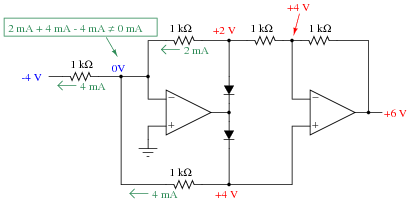
假设此精确整流器电路中的二极管D1失败。这将对输出电压产生什么影响?

|
|
提示:如果有帮助,请绘制与V相关的数字表in与vout,并将您的答案基于列表的结果。
对于任何正输入电压而言,输出电压不保留在确切的0伏上,而是输出等于(正)输入电压,前提是如图所示,它将其卸载。
挑战问题:该电路执行什么数学功能,diodeD1 failed open?
Note that the given failure does not render the circuit useless, but transforms its function into something different! This is an important lesson for students to understand: that component failures may not always results in complete circuit non-function. The circuit may continue to function, just differently. And, in some cases such as this, the new function may even appear to be intentional!
在以下输入电压条件下确定该电路的输出电压:

|
|
Hint: if you find this circuit too complex to analyze all at once, think of a way to simplify it so that you may analyze it one “piece” at a time.
The output voltage will be 2.2 volts, precisely.
后续问题:什么function does this circuit perform? Can you think of any practical applications for it?
Another facet of this question to ponder with your students is the simplification process, especially for those students who experience difficulty analyzing the whole circuit. What simplification methods did your students think of when they approached this problem? What conclusions may be drawn about the general concept of problem simplification (as a problem-solving technique)?
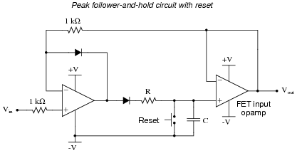
该电路称为peak follower-and-hold,以最大最大的正输入电压和“保持”该值在输出处“保持”,直到出现更大的正输入电压为止:
|
|
简要说明该电路的工作原理以及“重置”开关的目的和功能。另外,解释为什么要放大的最后阶段需要FET输入操作员。
I’ll let you figure out how the circuit works! With regard to the necessity of FET inputs, let me say this: if the bias current of the lastOPAMP太大了,随着时间的推移,该电路将“失去其记忆”对最后一个正峰值。
后续问题:您如何建议选择电阻R和电容器C的值?
Challenge question: redraw the circuit, replacing the mechanical reset switch with aJFETfor electronic reset capability.
询问您的学生是否可以考虑此类电路的任何实际应用。有许多!
I find it interesting that in two very respectable texts on opamp circuitry, I have found the following peak follower-and-hold circuit given as a practical example:

|
|
该电路包含两个错误:第一个是让重置开关转到地面,而不是-v。这使得重置函数将默认输出设置为0伏,这使电路不可能随后遵循并保持下面的任何输入信号。第二个错误是在重置开关之前没有电阻。如果没有电阻,关闭重置开关就将瞬时的短路放置在第一个Opamp的输出上。当然,电阻器的存在创造了一个被动集成阶段(RC时间常数),必须保持相当快的速度才能遵循和保留输入的快速变化,但这不是工程师的困难因素。
Published under the terms and conditions of the创作共用归因许可证